
Development of a novel Intelligent Lighting Control system with Imaging Sensor for optimum daylight exploitation and energy saving (ILCIS)
Harvesting daylight is a very important strategy to reduce artificial lighting consumption in buildings. Thus, the utilization of photosensors can achieve significant energy savings. The basic operation of a photosensor is the production of a unique signal that is related to the average amount of lighting in a space (in which it is placed), using its spatial and spectral response. This specific signal forces the ballasts or drivers to reduce the light output at the same level for all luminaires, although these should be regulated separately for optimum operation. Namely, a conventional lighting control system does not have the ability of distinguishing the areas that are darker or brighter inside the control zone. Hence, this system, among other problems, is unable to dim the light in the brighter areas or light up the darker ones simultaneously. In other words, it is impossible for the system to avoid optical discomfort and consume less energy, due to the exploitation of the daylight.
In this research project an innovative daylight responsive system with a CCD sensor instead of a photosensor was developed that is able to optimize the light output control of each luminaire. The heart of the system is an imaging sensor, installed in the ceiling, which is calibrated to measure photometric quantities. The optical field of the sensor is formed by a unique type of wide angle panomorph lens. This lens has the ability to capture an angle of 180ο and translate to a whole hemisphere. In addition, the captured image has a nonlinear compression factor (in contradiction with common fisheye lenses) and thus an almost constant quality is achieved in all areas of the image. The sensor and the lens are shown in Fig. 1.
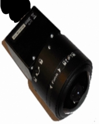
Fig. 1. The imaging sensor with the panomorph lens.
A special software was developed in order to exploit the abilities of the imaging sensor, the special behavior of the panomorph lens as well as to implement the control algorithms. The software integrates the photometric calibration of the imaging sensor, the control algorithm and the preparation of the DALI signals for each luminaire.
The major advantage of the described system (Fig.2) is that it behaves like multiple sensors and thus in a single loop of operation several task areas can be monitored, each one with a different desired set point (illuminance level). The principal of operation is the following: the system is calculating the illumination level of all working areas (defined by the user), compares them with the corresponding set point of the area (also defined by the user), calculates the optimum solution (according to the installed luminaires) and sends the appropriate control signal to each luminaire. The advantage of the system is that each working area has the desired illuminance.
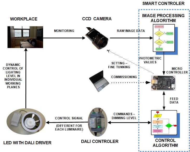
Fig 2. Block diagram of a lighting control system with imaging sensor
The artificial lighting installation of the office consists of six LED DALI luminaires (CREE LR200/27W 2000 lumens - 74 LPW). The imaging sensor is fitted in the center of the ceiling in vertical position looking directly towards the floor. A real image of the room is shown in Fig.3 using the actual smart imaging sensor. The sensor is able to measure virtually any point of the room.
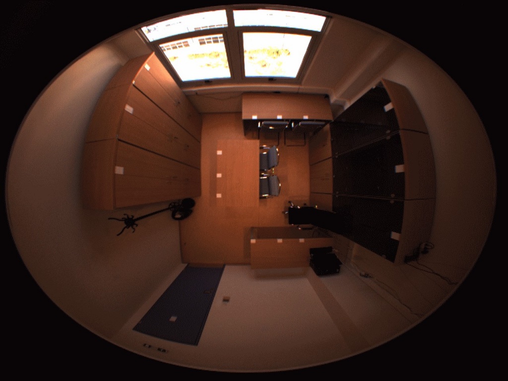
Fig. 3. Panomorph lens view of the test room.
A local DALI network is implemented using the 6 installed luminaires, a control PC station and a DALI translator. The luminaires are controlled from a central switch (only on and off) and from the custom software in all their parameters.
The test room has three individual working desks thus, according to EN-12464, each one must be illuminated according to its needs. For example, all three areas must be illuminated at a level of 500 lx, or any area with different lux (e.g. 300, 700, 500). All the control areas and the relative positions of the six luminaires are illustrated in Figure 4.
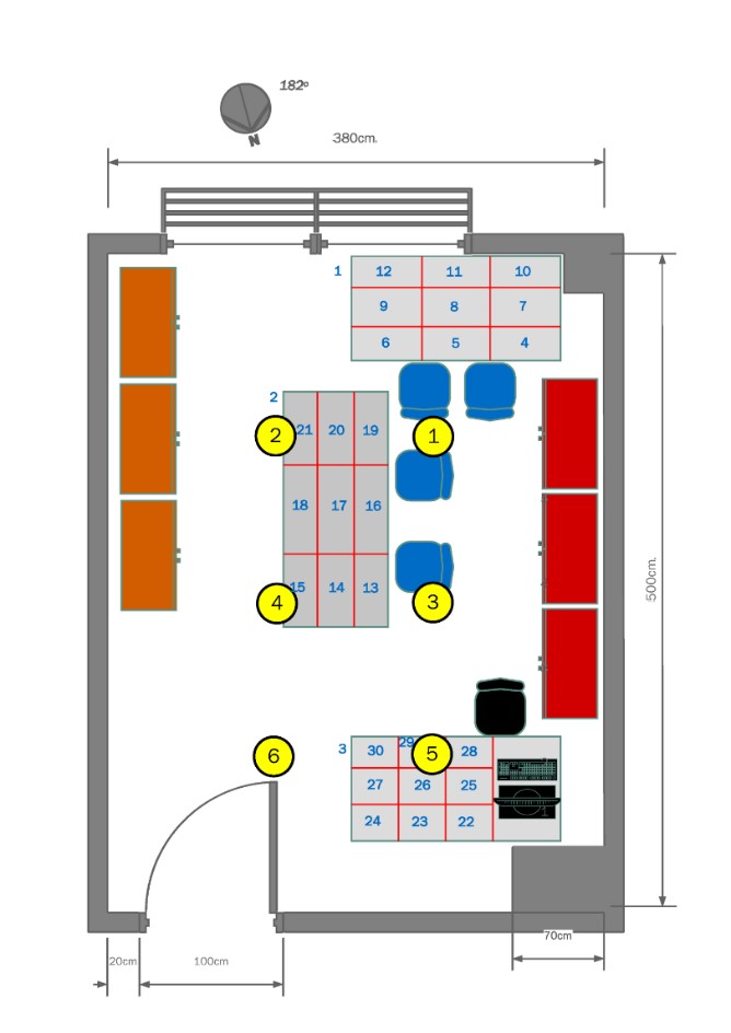
Fig. 4. Plane view of the test room with the 3 main control areas and the positions of the LED luminaires.
A very important section of the algorithm is the routine of measuring the current state of the illumination of the control areas. In order to achieve that a custom software script of several steps was developed. The software incorporates the HDR imaging technics and the calibration results, Fig. 5a and 5b.
By using this measurement routine the photometric parameters of the test room’s surfaces are calculated in short period of few seconds.
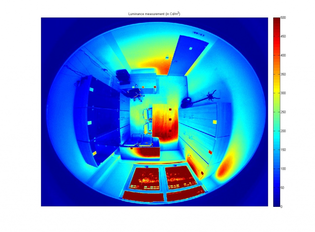
Fig. 5. Photometric measurements of the test room. a: Luminance image of the test room
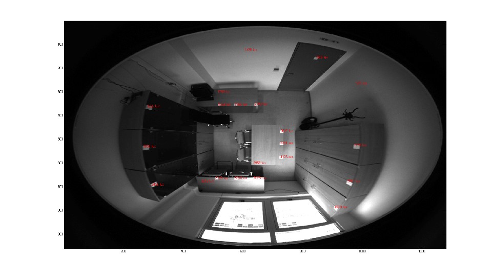
b: Illuminance at several points of the test room.
The system has the ability to calculate the illuminance in different areas and regulate the light output of each luminaire by processing different sections of the image that the CCD sensor perceives. In Fig. 6 the measurements during a day of January 2016 where three different illuminance levels were selected (300, 500, 400 lux) and the mean squares algorithm was used for the control of the luminaires. In Fig. 6 three control areas are shown (the red color corresponds to the set points, the green color corresponds to daylight and the blue color corresponds to artificial light) as well as the three uniformity areas, the control signals of the 6 luminaires and the overall energy consumption. The convergence of the control algorithm is impressive.
For comparison reasons a daylight harvesting system with a conventional photosensor was installed in an identical room. Both systems were operated within the same conditions (500 lux on each workplane area) and at the same time. In Fig. 7 the measurements of the room with the CCD sensor are shown and in Fig. 8 the measurements of the room with the conventional photosensor are shown. It is obvious that the system with the CCD sensor yields better results than the system with the conventional photosensor.
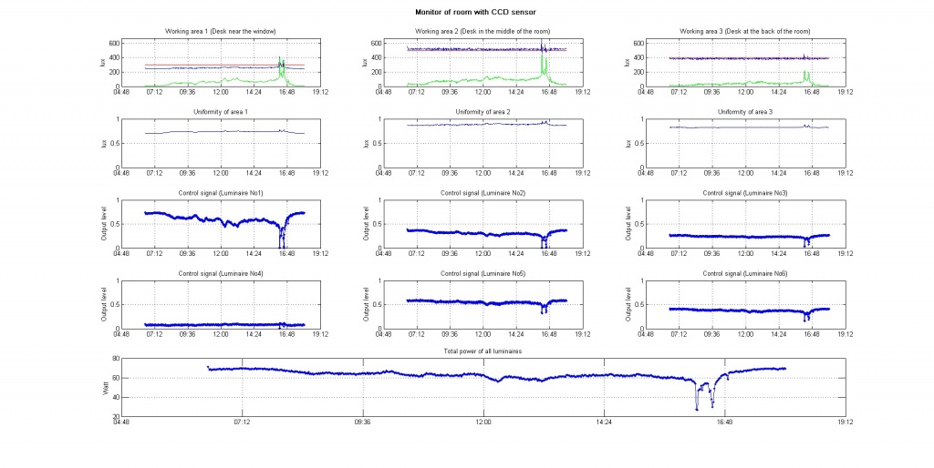
Fig. 6. Least squares and quadratic program. 10 January 2016.
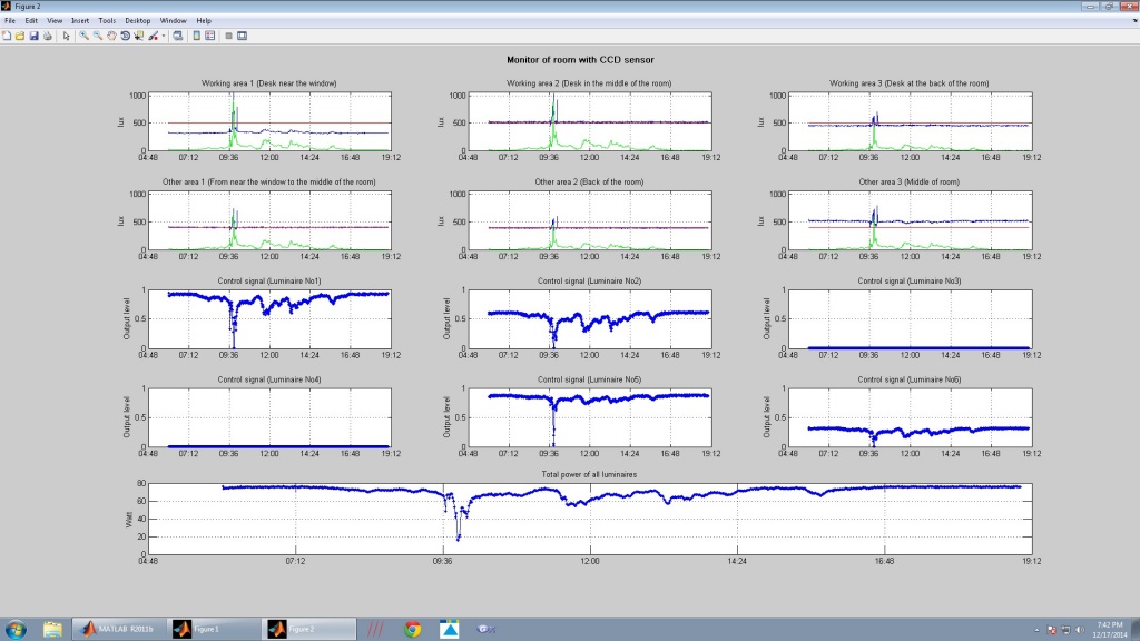
Fig. 7a. 17 December 2014 CCD control system
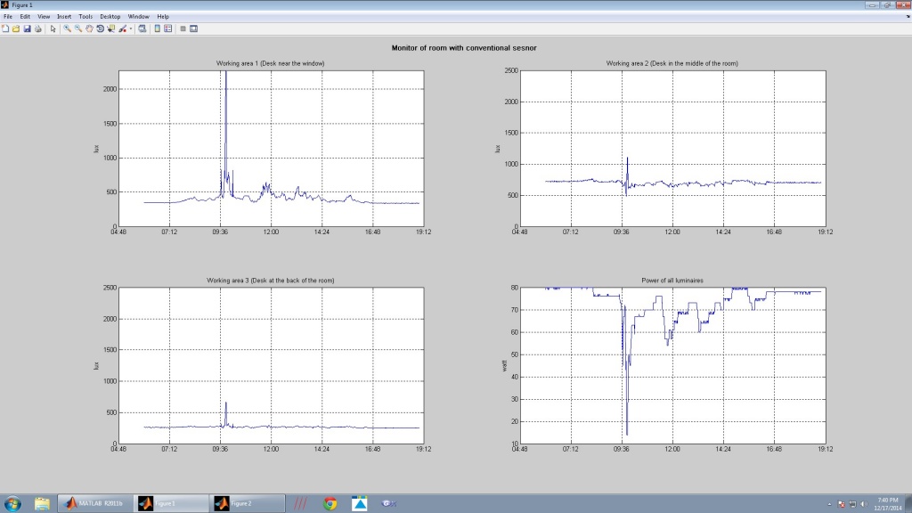
Fig. 7b. 17 December 2014 conventional control system
More information at :
Lighting Laboratory of the School of Electrical and Computer Engineering of the NTUA